Fire Procedures, Documents and Videos
Fire Hydrant Locations and Firehose Lengths
SUNDERLAND POINT: HYDRANT LOCATIONS AND FIREHOSE LENGTHS
Shortly after moving to Sunderland village, I went to a meeting of the SPCA Committee as an observer. During a discussion about firefighting I wondered if I might use my CAD skills in a desk-based exercise to determine how many firehoses might be required to reach different properties from the No.7 fire hydrants (H1 – 7 on attached plans). Katharine considered that this might be a worthwhile exercise, so I gave it a try.
Firstly, I obtained a small-scale plan showing the hydrants, and imported this into AutoCAD, and tried creating circles around the hydrant points, of concentric radii which matched the hose lengths (each firehose being 23m in length).
However, upon measuring to see how this was on the ground, it was clear that using a small-scale plan for this purpose wasn’t satisfactory. An attempt to obtain the free digital MasterMap data from the Ordnance Survey was frustrated by my inability to navigate the technical complexity of their vast website.
Fortunately, I’d overheard a chance remark by Peter Brennan to the effect that a detailed survey had at some point been undertaken at the Point. Upon emailing Peter, he kindly forwarded the full topographic survey, undertaken by Survey Operations in 2001, for LCC Engineering Services.
Within most urban areas, such a survey would have been redundant long ago, but given the slow pace of change at the Point, this survey was still very much valid, and today it would probably cost somewhere north of £20,000 to commission. The DWG file contains 63 separate CAD layers, which includes buildings, field boundaries, ponds, trackways, utility services, the entire length of the causeway, contours, and several thousand levels above Ordnance Datum.
After ‘turning off’ most of the CAD layers, and ‘cross hatching’ and numbering the existing buildings, it proved ideal for the purposes of superimposing the ‘firehose reach’ from each fire hydrant. The colours which I have used to indicate the radii arcs and firehouse routes are only intended to differentiate between the different hydrants used. The result comprises an A3 plan for the whole of the Point, plus a pair of A4 insets (at a larger scale), to cover First and Second Terrace (paper copies are posted up in the Fire Garage).
The plans flag up a number of issues. Firstly, the original given location of H4 (behind Dolphin House) was 40m from the gate by Nos. 2 & 3 The Lane. In fact, it is 49m from the gate, and 4m out from the fence. Worth remembering on a dark night!
Secondly, six hose lengths from H4 (as the crow flies) will only just reach No.5 The Lane, especially given that the hoses would be running uphill.
Thirdly, six hose lengths running from H4, through the gate by 2 & 3 The Lane, would hardly reach No.5 and the Mission Church (again, running uphill, so not 23m per hose length).
Fourthly, from H5, six hose lengths running up The Lane would barely reach No.4 The Lane (uphill again).
Fifthly, from H5, five hose lengths would just about reach No.3A, whereas six hoses would be required from H6.
Sixthly, the southernmost group of properties at Second Terrace could be covered by three hoses each from both H2 and H3.
Another, more general possibility arises. I’ve recently surveyed in the new infrastructure behind Second Terrace, and behind the Mission Church, the latter in connection with proposed solar panels. I could, over time, add in other infrastructure, including below-ground services, maintaining a useful digital record for future community use.
I would welcome any comments or suggestions to all of this. Thanks, Mark (No.17B).
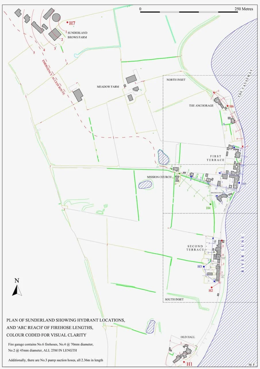
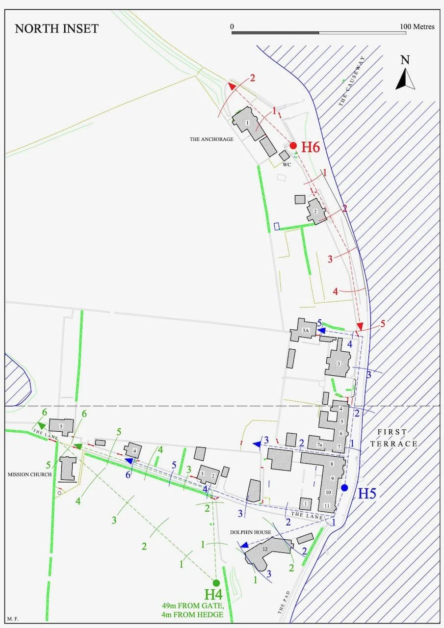
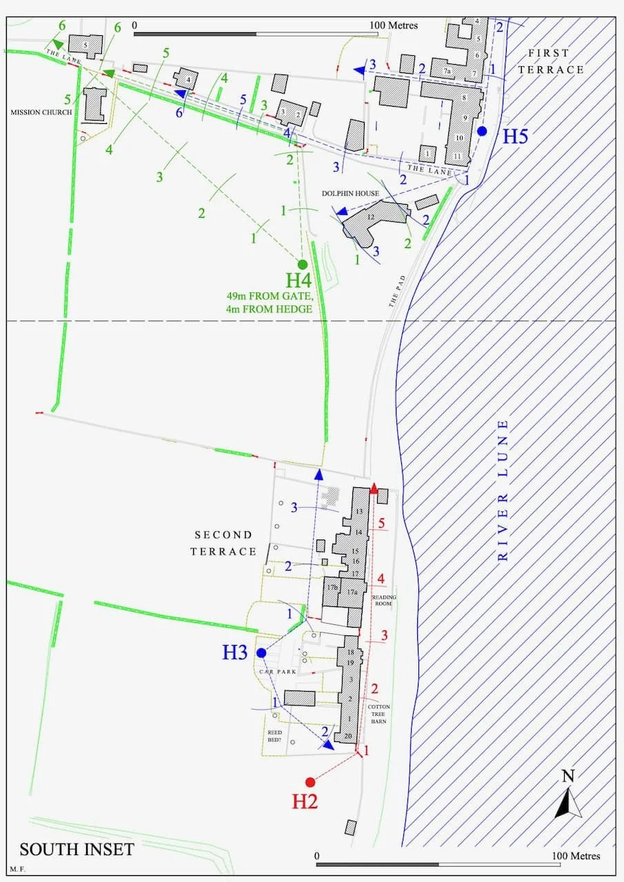
To download the maps - full map - north inset - south inset